Choreonoid 1.0 Basic Tutorial
Directions for opening the model file with Choreonoid to arrange the Scene screen are provided below.
Starting Choreonoid
Inputting
% ~/workspace/Choreonoid/bin/choreonoid
at the terminal, starts Choreonoid.
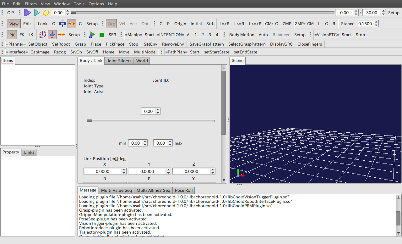
Among the five levels of toolbars available, primarily the Scene View bar of the second level, the Kinematics bar of the third level, the Planner bar of the fourth level, and the Items tab on the left pane are used in this text to manipulate the model displayed on the Scene tab on the right side of the screen. (The functions carried out by the respective buttons will be described later.)
- Scene View bar

- Kinematics bar

- Planner bar

Various messages are also displayed on the Message tab in the lower section of the Planner bar screen. Refer to Choreonoid Help for details about the toolbar.
Opening a model file
Models used by graspPlugin are opened from the File menu using Open–OpenHRP model file.
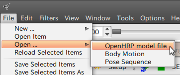
Once the model is opened, a checkbox and the model name are displayed in the Items tab. A 3D model is displayed at the origin on the Scene screen when the
checkbox is turned on.
Model files are arranged under extplugin/graspPlugin/Grasp.
- PA10 directory
- A model of the hand robot PA10, PA10.yaml, is available.
- Object directory
- Various model files (with extention “.wrl”) are available. There are two or three files with very similar names, but those that can be used with graspPlugin are file names that include “hrp.”
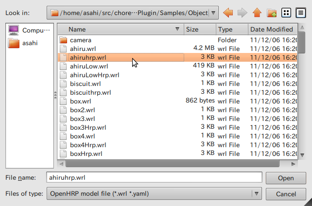
Even if ahiru.wrl is loaded, nothing else will happen if the following message is displayed.
Loading OpenHRP model file "/home/asa/workspace/Choreonoid/extplugin/graspPlugin/Grasp/Object/ahiru.wrl" Humanoid node is not found -> failed.
Object directory models
These are indicated by the names of the models. The file names are composed of a model name + hrp.wrl.- M0
- A rectangular parallelepiped (large)
- M1
- A rectangular parallelepiped (medium)
- M2
- A rectangular parallelepiped (small)
- ahiru
- A duck toy
- biscuit
- A box of biscuits (rectangular column)
- box
- A container
- can200
- A drink can
- cap
- A small cap
- chipstar2
- Potato chips in a case (cylinder)
- cup2
- A cup with a grip handle
- grcTemplate
- A box with one side open
- greentea350
- A PET bottle of green tea.
- Iemon
- A PET bottle for green tea (slightly smaller than greentea350)
- mug2
- A mug on its side
- packncho
- Sweets in a rectangular column packet
- packncho2
- Sweets in the rectangular parallelepiped packet, with two edges on one side remove
- petfruit
- A PET bottle (on its side)
- phone2
- A straight-type mobile phone (with antenna)
- remote
- A TV remote control
- souken
- A PET bottle with a dent in the middle
- table-can
- A table
Items tab
An opened list of models (items) is displayed on the Item tab in the left pane. Left click to select item A and manipulate it with the right click menu.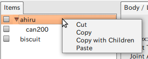
- Cut
- The selected item is deleted from the list and transferred to the clip board. Subordinate items can also be deleted at the same time.
- Copy
- The selected item is not deleted from the list but copied to the clipboard.
- Copy with subordinate
- The selected item, along with all its subordinates, are copied to the clipboard.
- Paste
- An item in the clipboard is added as a subordinate item to the selected item.
Furthermore, when a new model is opened while item A is still selected, the new model is added to item A as subordinate item B. Click on the triangular mark in front of the file name of item A to open and close the subordinate model list.
Scene screen
As described earlier, turning on the checkbox in the Items tab will display a 3D model on the Scene screen. Models that have just been loaded are all arranged at the origin. Smaller models may be buried underneath the larger models and so may not be readily visible.
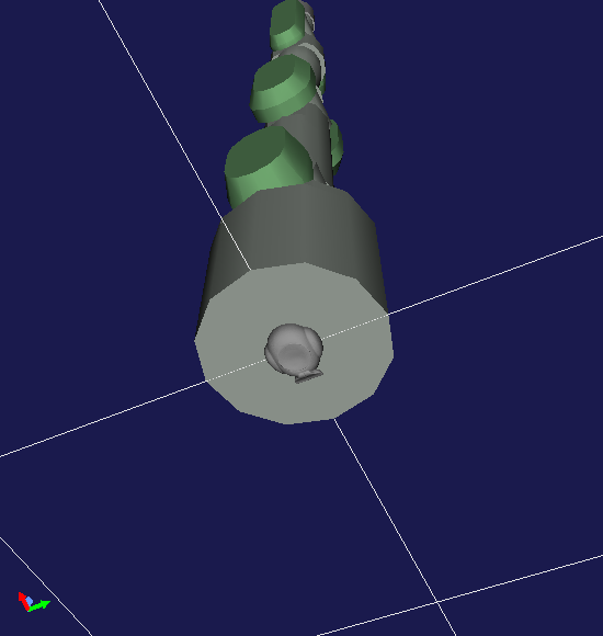
For example, in this diagram a duck is buried under the base of PA10. In such cases, first click the Edit button in the Scene View bar and switch to the Edit mode.
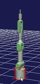
Red cubes appear around the model in the Edit mode. When the cursor of the mouse is placed on a model in this mode, the contour of the model is surrounded by a red line.
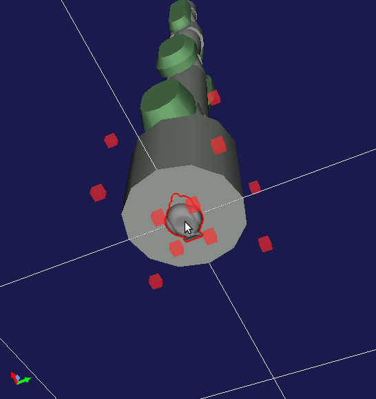
Once the presence of a previously invisible model is verified by changing the perspective or by zooming in the Scene screen, use the left button to drag and relocate it.
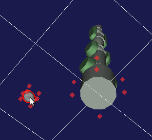
Press the View button in the Scene View bar to enter the View mode.
View mode
The Scene screen is initially in the View mode. Place the cursor of the mouse on the Scene screen, rotate a grid with the origin at the center using the left drag, and change perspective by moving it in a parallel direction using the center drag. The wheel can also be used to zoom in and out of the central point of the screen.
When the origin becomes lost, press the return to home view button of the Scene View bar to revert to the original conditions.
Models can be moved by using the Edit button on the Scene View bar to switch to the Edit mode.
Edit mode
Red dots are displayed around models in the Edit mode.
In addition, placing the cursor of the mouse on a model will surround it with a red line and cause it to be selected (an operation with no model selected is the same as an operation in the View mode). Operation changes according to the Kinematics mode in the Menu bar.
Switches the FK/IK modes automatically.
- Forward kinematics mode (FK)
- Forward kinematics mode. Taking the arm of a human, for example, determining the angle of the shoulder joint and the angle of the cubital joint determines the position of the wrist.
- Inverse kinematics mode (IK)
- Inverse kinematics mode. First moves the wrist to the targeted position and then uses that position to calculate the angles of the arm and the shoulder.
Switching to the IK mode and then left-dragging the model will relocate the position (drag the base in order to relocate the hand robot PA10). The movement axis of the model changes depending on the aspect, so please combine correctly the rotation and the aspect movement of the grid in order to move the model to your preferred location.
Adjusting the orientation of the model
Turn on Enable Attitude Edit in the IK mode and click on the model to adjust the orientation of the model. The model becomes surrounded by rings in three colors of red, blue and green. Drag these rings with the left drag and the orientation of the model changes accordingly.
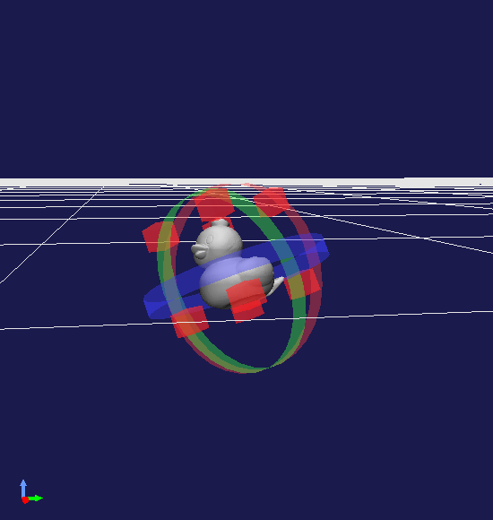
Red represents the roll (rolling), blue represents the yaw (yawing) and green represents the pitch (pitching).
Reverting to View mode
Press View in the Scene View bar or select View mode in the right click menu of the Scene screen to revert to the View mode.
Saving and loading a project
The conditions of the hand robot arranged on the Scene screen, as well as the model, can all be summarized and saved in a project file (with extension ".cnoid"). Select Save Project As in the File menu to display the File dialog and save the project with any name and in any directory. Similarly, a project file can be selected from Open Project in the same File menu to return the project back to the condition it was when the file was saved. Click on O.P. in the File bar to overwrite the project file instantly with the current conditions.