Grasp Motion Planning Tutorial by GraspConsumer Plug-in
Preparing the environment
These instructions start with the assumption that graspPlugin has already been installed. Refer to Installation of graspPlugin environment for details on how to install graspPlugin.
Running the software
In order to use graspPlugin it is necessary to run Choreonoid, the motion generating tool for the robot; also the grasp motion planning component, GraspPlannerComp; and to link these two tools with the RT system editor in Eclipse.
Run Choreonoid
Select “Terminal” in the accessory under the Application menu of Ubuntu and execute the following command:
% ~/workspace/Choreonoid/bin/choreonoid
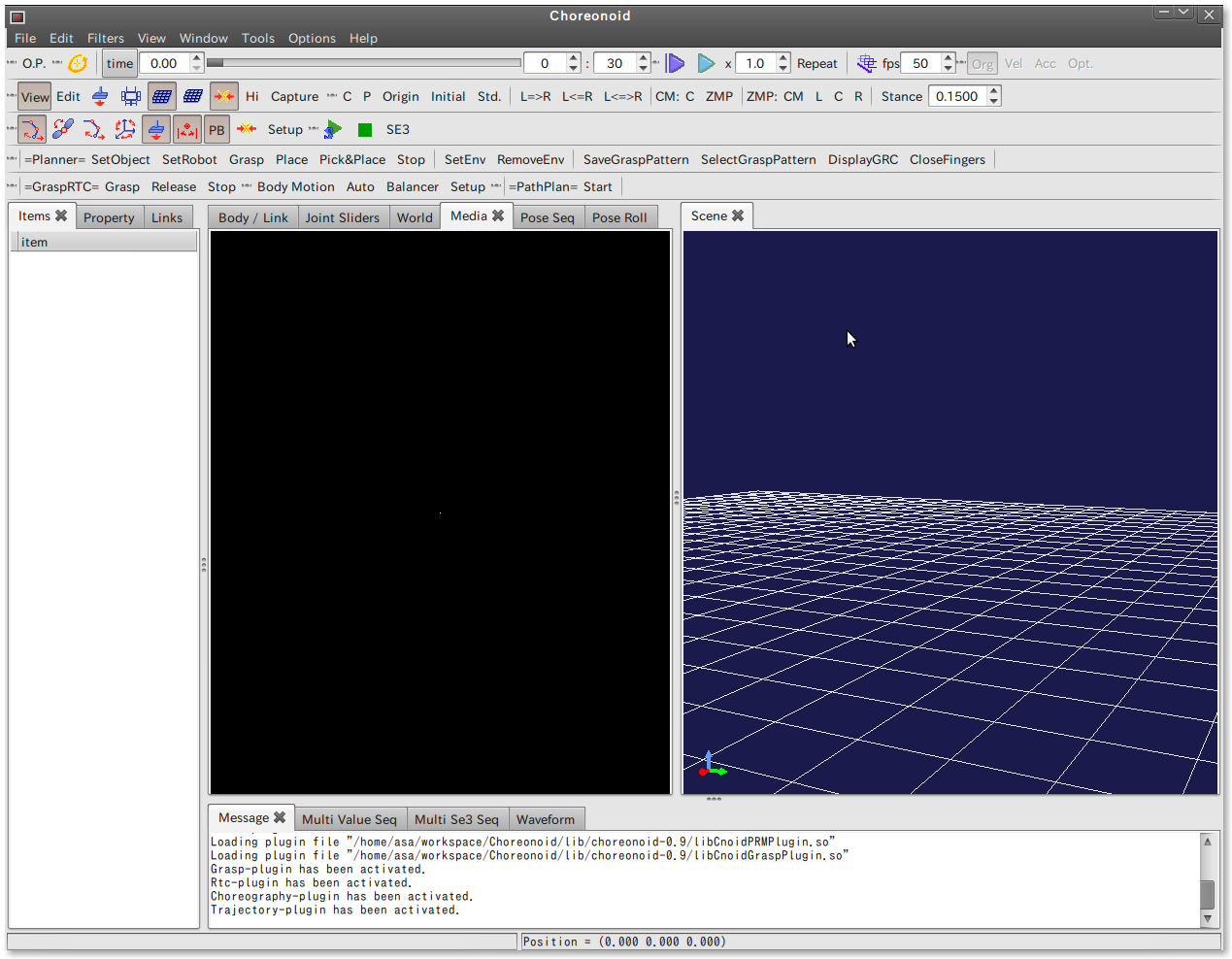
A new Choreonoid window will open.
Run GraspPlannerComp
Select “Open New Tab” in the File menu of the terminal to open another terminal, then execute the following command:
 % cd GraspConsumer/GraspPlan20100623
 % ./GraspPlannerComp
GraspPlannerComp does not display any messages, even when it is executed.
Run Eclipse
Once again, open a terminal from “Open New Tab” and execute the following command:
% cd ~/workspace/eclipse/eclipse
A new Eclipse window will open.
Set Eclipse
Open RT System Editor
Select “Open Perspective” and “Others” from the “Window” menu bar in Eclipse.
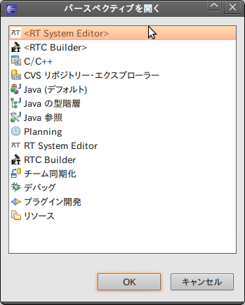
Select <RT System Editor> from the “Open Perspective” dialog box and press OK to display the following screen.
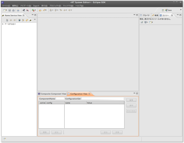
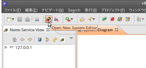
At this point, press the “ON” button in the tool bar to open “System Diagram.”
Set RT components
Click on the right pointing triangle in front of the item “127.0.0.1” in the Name Service View list, located on the left side of the Eclipse window. Two items appear: *EventChannelFactory- hotspot (note: this would be the name given to your computer)|host_cxt.
Next, when opening the right facing arrow on the item below, the following two items are displayed.
- GraspConsumer0|rtc
- GraspPlanner0|rtc
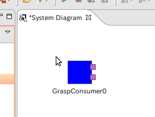
“GraspConsumer0|rtc” and “GraspPlanner0|rtc” are RT components that correspond to “Choreonoid” and “GraspPlannerComp,” respectively. First of all, drag and drop GraspConsumer0|rtc onto the System Diagram.
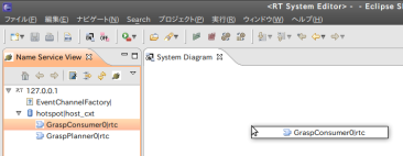
When it is dropped, a blue rectangular component, “GraspConsumer0” appears.
In the same way, drag and drop GraspPlanner0|rtc onto the System Diagram.
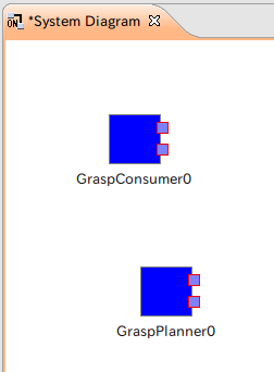
Two RT components will appear on the System Diagram.
Connect the ports of the RT components
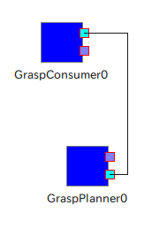
The two small squares located on the right side of each component represent the ports. GraspConsumer0 and GraspPlanner0 are both components that have two ports each.
These two ports are connected here. The sequence is not important, but ensure that the upper port of one component is dragged and dropped onto the upper port of the other component.
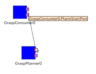
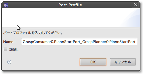
After doing that, the dialog, “enter port profile” is displayed. Press the OK button to connect both upper ports.
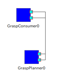
Connect the remaining lower ports in the same way, as in the arrangement shown in the diagram below.
If the ports are connected incorrectly...
If an upper port is connected to a lower port by mistake, this can be corrected.
Click on the line that forms the incorrect link.
A point will appear on the line at the center of the link between the ports.
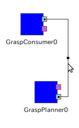
Right click on any of the three points to display a menu.
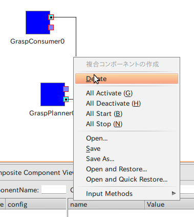
Select “Delete” in the menu to delete the line, then connect the ports correctly.
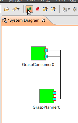
Activation
Once the upper and lower ports have been connected correctly, activate the RT components by clicking the “All Activate” button in the tool bar. If the components that were displayed in blue change to green, then the activation has been completed successfully.
Setting up Choreonoid
Load the models of the robot and the object in Choreonoid and perform the grasping motion.
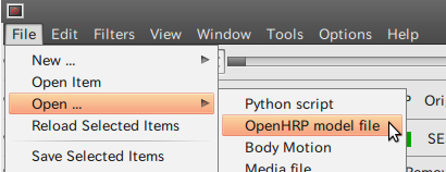
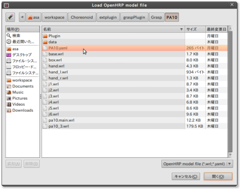
Load PA10
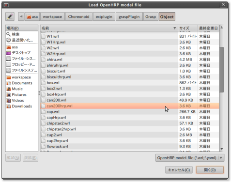
Load the model data of the PA10 robot first. Select “Open” and “Open HRP Model File” in the File menu of Choreonoid and select workspace/Choreonoid/extplugin /graspPlugin/Grasp/PA10/PA10.yaml
in the File dialog box to load the model of PA10.
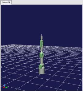
This creates a “PA10” check item in the Items tab on the left side of the Choreonoid window. Check this item to display the bundle of a green line, which represents a collision.
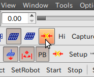
Click on the “collision visualization on/off”
button ![]() in the tool bar to turn off the collision display. The green lines disappear and an upright PA10 is displayed.
in the tool bar to turn off the collision display. The green lines disappear and an upright PA10 is displayed.
- Dragging with the left button: the bottom surface rotates about the origin.
- Dragging with the wheel button:The perspective is moved in a parallel direction.
- Turning the wheel:The perspective moves in the direction of depth on the screen.
The object can be viewed from any preferred direction by combining these operations.
Right click the Scene tab and select the Edit mode. The base of the PA10 becomes surrounded with red dots.
Click the “Inverse kinematics mode”  button in the toolbar to drag the base and move the PA10.
Move the object approximately one grid from its original location.

Loading a can object model
Now, select a can object model, can200hrp. Then, once again select “Open” and “Open HRP Model File” in the File menu and select workspace/Choreonoid/extplugin /graspPlugin/Grasp/Object/can200hrp.wrl in the File dialog box (note: It is not possible to load can200.wrl!).
As with the PA10, check “can200” that appears in the Items tab to display the black cylindrical model, can200.
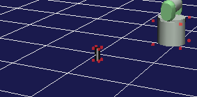
This also can be moved to any desired location in the Edit mode.
Set Robot and Set Object
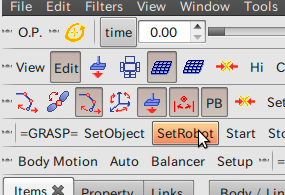
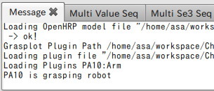
Click PA10 in the Items tab and click on “SetRobot” in the “=GRASP=” toolbar. The message, "PA10 is grasping robot" appears on the Message tab at the lower section of the screen.
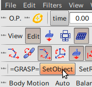
Next, click “can200” in the Items tab and this time click on “SetObject” in the “=GRASP=” toolbar. If “can200 is grasped object” is displayed on the Message tab, then the procedure has been completed successfully.
 [[Image:GraspedObjectMessage.png
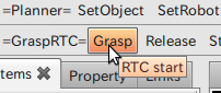
The preparations are now complete. Press the “Grasp” button in the “=GraspRTC=” toolbar to bring the PA10 into a grasping stance.

Similarly, it is possible to grasp a variety of objects by opening the file “*hrp.wrl”, listed under Grasp/Object and executing SetObject and Grasp.
In addition, to remove unnecessary objects, right click the object in the Items tab and select “Cut” in the Context menu.
Saving projects
There is a technique to perform all of the operations each time Choreonoid is used. Using “Save Project As” in the File menu of Choreonoid, makes it possible to save the current conditions of the robot and object of Choreonoid with any desired file name as a project file (with the extension cnoid). The current conditions can therefore be saved as a project file, ~/workspace/PA10.cnoid.
The settings are restored when Choreonoid is run again anytime subsequent to that by opening “Open Project” in the File menu and loading ~/workspace/PA10.cnoid.
Closing graspPlugin
Display the Eclipse System Diagram and press the “All Deactivate” button in the tool bar. When the components on the screen change from green to blue, close each of Choreonoid, GraspPlannerComp, and Eclipse.
This concludes the tutorial. Good job!
- Printer-friendly version
- Login to post comments
- 日本語