Hiro Service Demo Manual
This document is a demo manual for the pick-and-place manipulations of the dual-arm robot, HiroNX, which is part of “The Development Project for Intelligent Technologies for Next-Generation Robots.”
Reference material
This document targets users with a basic knowledge of RT Middleware (RTM) and RT Components (RTC). Refer to the link below for details on RTM and RTC.
OpenRTM-aist Official Website:
http://www.openrtm.org/openrtm/ja
Further, refer to all the documents below for details on the visual system, grasp planning system, and the robot control system used in the Demo.
- OpenVGR
- Please read the introduction
- Operating procedure
- Functional specification
- OpenVGR Coordinate Transformation Tool (OpenVGRextra)
- Please read the introduction
- How to use the cloth-marker detection program
- How to use the coordinate transformation matrix calculation program.
- Installation guide for graspPlugin for Choreonoid
- Instruction manual for the use of the HiroNXInterface
System Specification
This manual assumes that the computer's operating system is Ubuntu 10.04LTS. The dual-arm robotic demo is carried out using the software specified below.
- OpenRTM-aist 1.0.0-RELEASE
- Choreonoid 1.0.0
- graspPlugin for Choreonoid 1.0.0
- HiroNXInterface 1.0.0
- OpenVGR
- OpenVGRextra
It is assumed that (a) OpenRTM-aist1.0.0-RELEASE, Choreonoid1.0.0, graspPlugin for Choreonoid1.0.0, and HiroNXInterface 1.0.0 are installed on a host computer called “VisionPC” that is associated with HiroNX, and (b) OpenRTM-aist1.0.0-RELEASE, OpenVGR, and OpenVGRextra are installed on another host computer called “openvgr-host.” Further, it is assumed that the robot body’s power connections are made beforehand.
Preparation
Starting graspPlugin for Choreonoid
graspPlugin for Choreonoid is a software plug-in that provides functionalities such as grasp planning, and trajectory planning in robots in which the Choreonoid software has been installed. If the graspPlugin for Choreonoid has not been installed, install the same as per the installation guide. Then, change to the “~/src/choreonoid-1.0.0” directory (at the VisualPC terminal) and execute the following commands to start graspPlugin for Choreonoid.
% bin/choreonoid extplugin/graspPlugin/GripperManipulation/project /worldexpo.cnoid
The dual-arm robot HiroNX, a table, a box, and parts are displayed in the Scene View below.
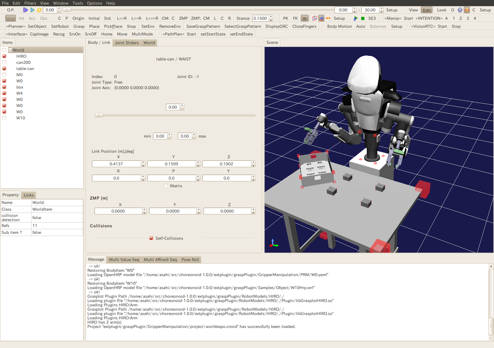
Figure 1. Startup Screen of graspPlugin for Choreonoid
HIROController0|rtc and VisionRecognitionTrigger0|rtc can be confirmed inside the localhost if the Eclipse RT System Editor is used.

Figure 2. Eclipse RT System editor
The RT component is represented on dragging and dropping these into the system diagram.

Figure 3. Eclipse system diagram
Starting HiroNXInterface
If HiroNXInterface has not already been installed, install the same as per the instruction manual. HiroNXInterface has two RT modules, namely HiroNXProvider and HiroNXGUI. Start two VisionPC terminals and launch these modules, one in each terminal. Then, using the RT System editor, connect the upper and lower ports of HiroNXGUI0 and HiroNXProvider, respectively. Then, connect the upper and lower ports of HIROController0 and HiroNXProvider in a similar manner. The system diagram will look like the one shown below.

Figure 4. Connection between the components included in HiroNXInterface.
Then, activate these RT modules and set up the dual-arm robot, HiroNX, from the HiroNXGUI.

Figure 5. HiroNXGUI
Press the buttons from top to bottom, from the “Setup” button to the “Servo Hands ON” button.
1. [Setup Robot]: Connect HiroNXGUI and the Hiro body.
2. [Calibrate Joints]: Perform joint calibration (accompanied by the operation of HiroNX)
3. [Go Initial]: Switch to the initial pose.
4. [Servo Hands/ ON]: Switch “ON” the Servo Hand so that the left and right hands can be opened and closed.
Starting OpenVGR
Install OpenVGR and OpenVGRextra in openvgr-host by (i) following the OpenVGR operating procedure and (ii) reading the OpenVGRextra introduction mentioned in section 1.2. Invoke the RT components included in OpenVGR and OpenVGRextra at the openvgr-host terminal. Please note that all the RT components on openvgr-host should have references to the VisionPC “name server” while configuring rtc.conf. Use the RT system editor to connect the RT modules as shown below and activate them.

Figure 6. RT components connection diagram
Table setup
Prepare a 1-m-high table and place it so that the pedestal of HIRO touches it. Using the front-right corner of the pedestal as a reference, place the box on the table at a position 170 mm to the right and 170 mm to the front, with the longer side inclined at 45° (refer to Figure 7).

Figure 7. Position of the box
Next, place the parts on the table. Though the parts can be placed anywhere within reach of the robot’s arm and camera's view, they will be difficult to grasp if many parts are crowded together. This is to ensure that grasp planning is carried out by recognizing individual parts.
Figure 8. Illustration for arranging the parts
graspPlugin for Choreonoid’s toolbar
The demo progresses further by primarily pressing the toolbar buttons of graspPlugin for Choreonoid.

Figure 9. Toolbar of graspPlugin for Choreonoid
Figure 9 shows an illustration of a graspPlugin for Choreonoid toolbar. Though the arrangement of the tools in the toolbar varies depending on the number of plug-ins and the data fetching sequence, this is a typical graspPlugin for Choreonoid toolbar.
The toolbar buttons given below are primarily used in this demo.
| Position in the figure | Title | Plug-in invoked | Remarks |
|---|---|---|---|
| Second from the right in the middle row | =VisionRTC= | VisionTrigger | Interfaces with the visual system |
| First from the right in the bottom row | =PathPlan= | PRM | Performs trajectory planning |
| Second from the right in the bottom row | =Interface= | RobotInterface | Interfaces with the dual-arm robot control system |
| First from the left in the bottom row | =Planner= | Grasp, GripperManipulation | Performs grasp planning |
In addition, as explained later in this document, the “Play” button of the “SceneView” bar and the Slidebar may be used to confirm the grasp planning before it is generated.
Pick-and-place Demo
Specifying the part placement location
In the SceneView present on the right of the graspPlugin for Choreonoid screen, there is a box on the table (to the right of HiroNX) for arranging the parts. There are four circular and four rectangular cavities in the box for placing circular and rectangular parts, respectively. Manually specify any one of the cavities as the location for placing a rectangular part. To achieve this, place the mouse cursor on a rectangular cavity and left click while pressing the “Ctrl” key. In the figure, there is an upright pin at the position indicated by the mouse cursor.

Figure 10. Specify the location to place the part
Visual recognition
When the “Start” button on the VisionRTC toolbar is pressed, visual recognition is carried out via OpenVGR and the position of the parts in the SceneView screen reflect the actual positions of the parts on the table.
Grasp planning
When the “Grasp” button of the “Planner” toolbar is pressed, the gra
sping posture (for grasping the recognized part) is planned. When the “Start” button of the “PathPlan” toolbar is pressed, the trajectory of the robot (starting from the initial position to placing the part in the box) is planned. It is possible to verify how HiroNX grasps the part and places it in the box through an animation in the SceneView screen by pressing the “play” button and moving the Slidebar at the top of the screen. It is necessary to verify the planned operation before actually making the robot operate.
![]()
Robotic motion
After verifying that there is no abnormality in the operation, make HiroNX perform the actual grasping operation. Press the “Move” button on the Interface toolbar (right end of the image).With this, HiroNX will actually start its operation.
![]()
Other Operations
Two other operations are implemented, apart from the pick-and-place operation, which are (i) dismantling an assembly made of four parts and (ii) moving the box.
Dismantling the assembled parts
This can be achieved by following the steps below.
1.Check the checkbox on the left of W10 of the itemView present on the left side of the Choreonoid window. A model with four parts assembled in the box is then displayed in the SceneView.
2.Click the W10 portion with a mouse and press the “SetObject” button of the “Planner” bar on the resulting colored background. W10 is recognized as the target object for graspPlugin in this manner.
3.Press the “Start” button of the VisionRTC bar to see the four parts in the assembled state, reflected in the SceneView.
4.Press the “Grasp” button of the “Planner” bar followed by the “Start” button of the “PathPlan” bar. This plans an operation for dismantling the assembled parts. The planned operation can be verified by pressing the “Play” button and moving the “Slide” bar.
5.Press the “Move” button of the “Interface” bar to make HiroNX execute the planned operation.
Moving the box
This can be achieved by following the steps below.
1.Click the W4 portion with a mouse and press the “SetObject” button of the “Planner” bar on the resulting colored background. This results in W4 being recognized as the target object for graspPlugin.
2.Press the “Grasp” button of the “Planner” bar followed by the “Start” button of the “PathPlan” bar. This plans an operation to move the box. The planned operation can be verified by pressing the “Play” button and moving the “Slide” bar.
3.Press the “Move” button of the “Interface” bar to make HiroNX execute the planned operation.
Calibrating the robot with respect to the visual system
It is necessary to calibrate the visual system and the robot in preparation for the demo. First, uncomment the “define” statement defining the CALIB_MODE in graspPlugin/GripperManipulation/ManipController.cpp and compile the GripperManipulation plug-in.
Then, use graspPlugin/GripperManipulation/project/worldexpo.cnoid as the project file and start Choreonoid. Press the “Grasp” button of the “Planner” bar. Then, in the SceneView of Choreonoid, carry out an operation similar to that of robot calibration. During this time, a sequence of joint angle and marker positions is displayed in the terminal. Use this sequence of joint angles and operate the robot; record the marker positions measured by the visual system. Then, use the sequence of marker positions displayed at the terminal to compute the calibration matrix.
Exiting the Demo
Shut down the software and hardware used in the sequence given below.
- 1.Exit OpenVGR
- 2.Exit OpenVGRextra
- 3.Exit Choreonoid
- 4.Use HiroNXGUI and shut down HiroNX in the order given below.
- 1. [Go Off Pose] – Switch to standby Pose
- 2. [Servo Hands/OFF] – Switch OFF the hand servos
- 3. [Servo/OFF] – Switch off the HiroNX body servos
- 4. [Shutdown] – Shutdown HiroNX (also exit the HiroNXGUI)
- 5. Exit HiroNXProvider
With this, the dual-arm Robot demo is complete.
- Printer-friendly version
- Login to post comments